If you're reading this for the first time, you might want to start at the beginning. You can use the "Blog Archive" list to the right to quickly navigate around. To find the start, click on 2010 (1) to go to the First Post. Use the "Blog Archive" list again (2012) to return to here or anywhere in between. Sorry if this is a little confusing but its just the way that blogs apparently work. The last post is always the first post you see.
Posts are made around the beginning and middle of each month give or take a few days.
Please keep in mind when reading this particular post that I am but an enthusiastic amateur albeit taking a good deal of care. My goal is to build a very reliable smooth running engine, but if I make a mistake, it will probably be a big one!
Although only last October, it seems to be an awfully long time ago (especially in memory recall terms) that I dismantled the engine. I was encouraged to do the re-build myself after several offers of technical assistance from friends and acquaintances. My initial requirement was to find a first rate machine shop, ideally with some XK engine knowledge. After some research I decided on a company quite local to home, AMAC in Northallerton. Always very busy and with an excellent reputation, I was forewarned that it may be gone a while, and so it was. As I have the luxury of time, this was not really a problem. Four months later and right on cue, I got the call at the end of February advising that the Block, crank and other associated bottom half components were ready for collection. The cylinder head repairs and machining were still to do, but this would give me plenty of stuff to be going on with.
Courtesy of friend Dan at Classic Jaguar in Texas I received in December, a set of beautifully engineered Ross forged alloy pistons and Total Seal rings with individual piston weights differing no more than half a gram. AMAC do a similar balancing job on the con-rods, after which they dynamically balance the crank with flywheel, clutch pressure plate and front damper. Dan also supplied a nicely engineered modern rear oil seal conversion, which just required the scroll to be machined off the crank and the appropriate seal area to be turned down to 2.632 inches. With the front oil seal also upgraded to a modern type my past 'persona non grata' status at some posh driveways may be reviewed.
 |
| Wonder what Sigmund would make of this? |
 |
| And this ! Surely a Turner prize photograph. |
The main bearing shells are installed dry into the block and caps and Graphogen grease is coated onto the bearing surfaces. The top half of the new rear oil seal is fitted using Locktite on the machine screws. The crank is gingerly lowered into place and the caps (centre with new thrust bearings) are fitted. End-float is checked and measures an ideal 0.08mm, just over 3 thou.
Lightly lubed bolts and hardened parallel washers (in place of the original tab washers) are gradually torqued down to 72 LB FT. The bottom half of the rear seal conversion is installed, again using Locktite. Afternoon visitors take turns to spin the crank and marvel at the smoothness of reciprocation. I should think in all, around an hours work for a professional. Allowing for thinking, socialising and tea drinking, a good days work for me.
 |
| End float measurement. Also clearly shows bottom half of oil seal conversion and Graphogen assembly lube on main bearing. |
 |
| Total Seal rings come with very specific fitting instructions. Two Spirolox wrist pin retainers each side replace usual circlips. Note new type of nut for con-rod bolts. No washers or lock tabs of any sort. Seems odd but I am assured it is totally correct. |
 |
| Ross forged piston with Total Seal rings |
 |
| Spirolox gudgeon pin retainer opened up ready to be pushed in to the groove bit by bit. Easy when you know how. |
 |
| Very accurate but Heath Robinson device to measure piston to deck height. Steel block holding gauge was a tow ball spacer in an earlier life. |

In fact, it turns out to be quite straightforward. With Pistons 1 and 6 at TDC the distributor drive shaft should look like the picture below with the drive line at approximately the 5 minutes to 5 position. Its only when you come to set the valve timing that you need to ensure that the larger segment is to the right. If it's a little out, your distributor will point in not quite the right direction. Not ideal, but not really a problem. However, if you installed it entirely the wrong way round, your distributor would need to be 180 degrees about face, and that wouldn't be good.
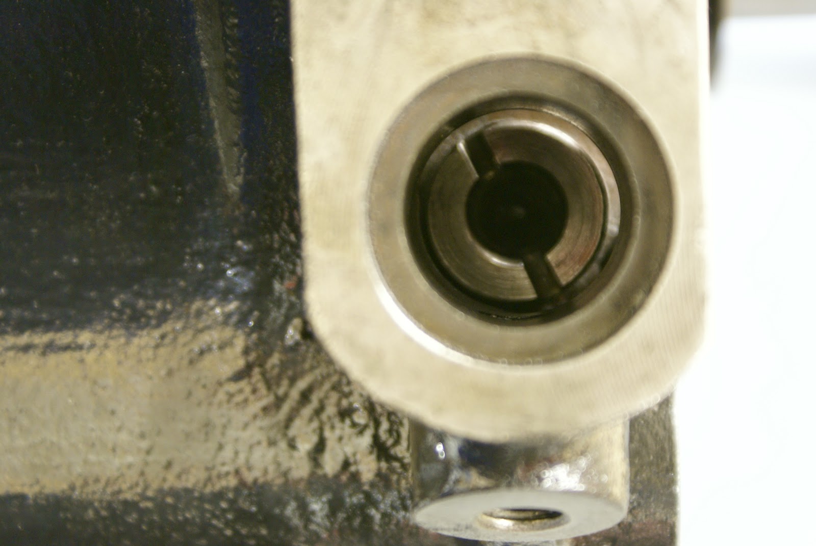 |
| With 1 & 6 at TDC, position of distributor drive shaft - 5 minutes to 5 Larger segment to the right when you get round to valve timing. |
 |
| Distributor drive - awaiting lock washer and nut. Note the increased O/D collar on the crank to accommodate a modern oil seal. |
 |
| New oil pump and incredible floating err - float |
Next scary task is try and make some sense of all of those complicated looking sprockets, chains and things driven from the crank shaft.