Tuesday 18 October 2011

POST 16 OCTOBER 2011 ENGINE REBUILD 2


My initial intention was to send my engine to Dan at Classic Jaguar in Texas for the full CJ works and initially it looked as if shipping costs would be reasonable.  A basic quote to ship from here (Middlesbrough) to Houston docks and return came out at less than £1K but when all manner of other charges were factored in, including shipping from Houston to Austin, the price more than doubled.  This coupled with the satisfaction I derive from mechanical things in general made the decision for a carefully planned and executed home build easy.

     
My Valve spring compressor wouldn’t look at moving the caps off the collets so an alternative design was called for which resulted in this Heath Robinson affair – inelegant but with the shock of a 12lb hammer, very effective.  A chamber shaped block of wood stops the valve from moving.


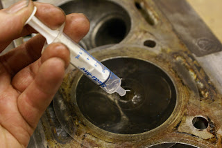
The original compression ratio was 8:1 and I would prefer something between 8.5 and 9.0 but I need to know if the head and block have been previously skimmed, so knowing the current actual ratio is essential.  A little research on google comes up with a process which involves measuring the volume of the cylinder head chamber using very cold ?? liquid paraffin and a syringe.  (The lady in the chemists clearly didn’t accept my explanation when she helpfully enquired as to the intended application of these items)  Also included in the calculation are the swept volume, gasket thickness, piston at TDC to deck measurement and volume of the piston dome.   Only the piston dome calculation (volume of part of a sphere) complicates things but I get there in the end.  Chamber volume averages out at 0.016 Litres (6.469 Cubic Inches) After transferring the calculations to a spread sheet, and a little creative manipulation, miraculously it averages out between all cylinders at 8:1
Calculations show around plus / minus one percent difference
in compression ratio between cylinders.  Does this matter? 
 I have absolutely no idea - Any comments appreciated.


Largest syringe I could find on a Saturday morning was 5 mL but a 150Ml
 baby milk bottle measure plus the specific gravity of cold liquid paraffin
and letter scales all combined to hopefully give me an accurate result.


It always amazes me how simply warming pistons in a bucket of hot water expands them enough for the gudgeon pin to easily punch out.  More with an eye on protecting my new forged pistons when I need to re-assemble, it seemed like a good idea knock up a simple wooden jig to sit them in.  If you’re wondering, the metal contraption adjacent is part of an old machine press tool and just comes in handy.  

Engine broken down entirely into its comonent parts


With some more help from Dan I have produced what I hope is a fairly comprehensive list of work for the machine shop and email this to a few likely candidates.  They’ll probably read it and think – now this lad looks like trouble! 


Block
Bores currently +15
Chemical / vat clean
Crack test deck surface
Check alignment of main bearings and hone as required
Fit new liner to No 3 (small “ding” in cylinder wall)
Bore to Circa +30 and hone to match individual pistons supplied
Skim deck

Con Rods
Crack test
Check for alignment
Re-Size & Re-bush

Crank Shaft
Existing – Mains are standard.  Big Ends are -10
Remove plugs
Clean
Crack test
Machine to correct Main and big end bearing clearances most likely -10 and -20
Balance with Flywheel, clutch and pressure plate

Head
Weld up “cruddy” water ways and machine
Pressure Test
Replace Valve seats and cut as req.
Replace Valve guides and set stem to guide clearance
Skim


Allow for full recording / documenting of all measurements / outcomes.
Initial costing to be based on all parts to be free issued by me
Crankshaft rear oil seal conversion – exact spec requirements TBC

Monday 3 October 2011

POST 15 - OCTOBER 2011 - ENGINE REBUILD

If you're reading this for the first time, you probably want to see the blog from the beginning.  You can use the "Blog Archive" list to the right to quickly navigate around.  To find the start, click on 2010 (1) to go to the First Post.  Use the "Blog Archive" list again (2011) to return to here.  Go to the bottom and work your way back up again.  Sorry if this is a little confusing but its just the way that blogs apparently work so, that the latest post is the first thing you see.

I was just turned seventeen when I first dismantled an engine.  It was from my newly acquired 1934 Singer.  Nothing much wrong with it, but it just seemed like an interesting thing to do.  My automotive engineering experience at that time was limited to watching an agricultural engineer take apart a Ferguson Tractor Engine.  Looked quite simple really.  You just take everything to pieces and throw all the bits in the sump.  It didn’t occur to me that he’d done this dozens of times before and  I can clearly remember him saying that you don't need to make notes because an engine can only go together one way, but my engine must have been the exception that proves the rule.  Fortunately my £35 outlay for the car included enough bits to almost build another, including a spare engine which was also then dismantled to see how the first one went back together.  The only bit leftover was a small bronze bush which turned out to be the gearbox end shaft bush.  I still have it.
Doing the 120 engine is for me the highlight of the restoration.  I’ve not done an XK engine before but have read a good deal about them and never missed an opportunity to discuss the detail with the many knowledgeable enthusiasts I’ve met since getting into XK’s generally.
It all comes apart fairly easily considering the time it's been standing.  Everything looks pretty much as it should until I remove number three piston.  It looks different from the previous two and closer inspection of the bore shows a small “ding” in the front face around two inches down.  Looks like it could have been caused by the end of a broken valve.  Examination of the Head also shows some valve head shaped marks in number thee chamber.  Measuring the depth of the “ding” as best I can shows it to max out around twelve thou.  Its already bored fifteen thou oversize so it won't be possible to clear the problem by taking it to thirty (the max size for forged pistons I believe).  Perhaps it won't be a problem at all, not being on a thrust face of the bore.  I whizz off an email to Dan in Texas with the question and get a very quick and definite "your divot is not acceptable" response.  He says It will be quite straight forward to install a single liner to resolve the problem. 

Spotless engine oil - could it be that it had an oil change
back in 1965 when it was taken off the road?

I guess the answer is yes, and a filter change.  This filter has
 never had oil throughit but has obviously been fitted a very
 long time.
First discovery - end of timing chain spring tensioner broken
off.  A dig around in the sump with a magnet finds the missing bit


I really didn't think that my engine stand would be up to the job,
but it was more than adequate once I'd modified the four fixing bits.


Ding (divot in USA parlance) can clearly be seen.  Also some
rough areas below.  This bore looks generally different to the others.


Number three piston also looks quite different from the rest.
Could it be that its been replaced after a dropped valve and
has done relatively few miles since?
 
All I need to do now is to find a machine shop that I can entrust the work to.  Sounds simple enough but I've heard far too many horror stories, usually involving lots of expensive damage, invariably in the middle of the night, always in some foriegn part, followed by endless recriminations and costly litigation.  Strangely, its the journalists who report in the "our cars" sections of classic car magazines who seem to be singled out for dodgy engine jobs, or are they just the ones we actually get to read about?