Tuesday 17 April 2012

POST 28 - APRIL 2012 - ENGINE BUILD PART 4 AND REPRO PARTS PROBLEMS

Assembling the timing gear and fitting to the engine block

I may be unlucky, but with a couple of notable exceptions, the general quality of 'repro' parts I've had delivered from UK suppliers leaves a good deal to be desired.  I guess to some extent it has always been so, with constant downward pressure on prices limiting what can be achieved in quality.  Could it be that quality is considered less important for vehicles that typically cover small annual mileages.  Failure for example, of a relatively insignificant engine part can have disastrous and very expensive consequences, but the passage of time means that we we are less likely to hold the culprits to account.  I've dealt with most of the purveyors of classic car parts over the years, and I suspect that many have quite a few suppliers in common.  Imported parts from the Far East, India and China have garnered a reputation for poor quality, but I am told that many Jaguar repro parts are manufactured around the Coventry area by ex employees of the once Great British motor industry (could there be a clue here?).  Conversely, parts purchased  from the USA have been flawless. 

Surely it would be better to pay a little more, then spend a good deal less time checking and fettling facsimile parts to make them good for purpose. 
So what has brought about this 'rant'.
I required new chains, guides and a tensioner conversion for my engine rebuild. Result:

The chains supplied have arrows on the links indicating I suppose the direction of travel (why else would they be there?) but every few links they randomly change direction.  This and the split link arrangement left me feeling decidedly uncomfortable.  After some deliberation, I bought another pair, original Reynolds for the top and a split link free repro (no originals available) for the bottom.

The bottom chain guide was around 10 degrees off being at right angles to it's mounting base, meaning if not 'adjusted' the chain would have worn the guide away on the inside first.

The top chain guides, combined with the spacers supplied are around 1mm less deep than the original brass items (1.125") which means the aluminium castings they are sandwiched between could be bent / stressed.  Also the rubber face sits around 125 thou higher than the original.  Whilst easily remedied, is this intentional, and better than the original, or an error.  How do I find out? 

New and old upper chain guides.  Unusually, a post on Jag lovers
forum asking what might be used to replace the original worn nylon
type material on the lovely brass casting drew a complete blank.
Have I inadvertently upset the usual sages. 


New upper guides are 35 thou less deep (should be 1.125")
Does it matter?  I'd love to know !

New upper guides are also around 0.125" higher than originals.
Is this an improved design or just a mistake.
Again, I would really like to know.
The hydraulic conversion kit brass mounting block required a good deal of relieving to allow it to fit, not really a problem, but when the hydraulic bit was installed, it was tight up against its back stop and still exerting excessive pressure on the chain.  I would guess the rubber pad's life would not be long (but possibly a couple of years for a low mileage classic). 
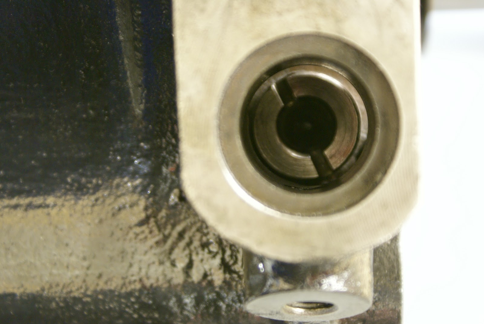
The tensioner conversion takes its oil from the feed originally used for an oil spray bar, which is dispensed with, so no more oil for the crankshaft sprocket and distributor drive gear.  I guess this must be OK but it would be good to know for certain.

Brass mounting block needed quite a bit taking off to make it fit.
Is this peculiar to my engine or all engines ?

All of the above issues are to some extent sorted.  As an amateur restorer my time is effectively free but I wouldn't like to be footing the bill from a professional for all this additional remedial work.

So - having got that off my chest, back to the engine build.   I have a couple of books that helped enormously, each with its own slant on the processes involved. 


JEC publication - 'On Jaguar XK120 Restoration' - ISBN 1 873098 38 1
A fairly comprehensive 120 restoration guide with some good detail pics.

Excellent and well known Dave Pollard book  'Jaguar XK Engine'
ISBN 1 85960 007 7   Don't start work without it.
Both books mainly relate to later XK engines, so I am not sure if my very early engine has some minor differences, sometimes requiring a slightly different approach.  In summary, this seems to be the preferred procedure and it mostly worked for me:

First - assemble rear plate - Graphogen on all moving parts

Next fit the front plate and adjuster mechanism.
Note marks on serrated wheel probably due to attempts
to adjust with incorrect tool.  Fortunately no real damage.

then - hang  the assembly from crank sprocket
(Engine upside down)

Fit assembly.  Note - lower guide in place - parallel in both plains
to chain but not quite touching.

Finally fit Hydraulic tensioner conversion.  Note how the rubber foot
is totally back in it's housing.  Chain tension is just acceptable after
enlarging all tensioner assembly holes to allow it to move around
1.5mm to left.
Some points not mentioned in either book:
Double check and measure every repro part for quality, dimensions etc. against your original parts and remember to grumble at your supplier if you need to tweak them.  They might eventually start to get the message.
If you fit the hydraulic chain tensioner
Install the bottom chain on its intermediate sprocket before you finally fit it's shaft in place and secure with a circlip.  (my none split link chain wouldn't quite go on with the sprocket fitted first)

This part of the engine build has taken quite a bit longer than I had planned and was not particularly enjoyable, so it's time for a little light relief. 
The body shop were never really happy with the boot lid, so I plan to make a new wood frame and fit it with a good skin, but this first needs to remove from yet another lid I found locally.  Next post showing this to completion (hopefully) will be at the beginning of May.

Sunday 1 April 2012

POST 27 - APRIL 2012 - ENGINE REBUILD PART 3 - SHORT MOTOR

New to Blogs?
If you're reading this for the first time, you might want to start at the beginning. You can use the "Blog Archive" list to the right to quickly navigate around. To find the start, click on 2010 (1) to go to the First Post. Use the "Blog Archive" list again (2012) to return to here or anywhere in between. Sorry if this is a little confusing but its just the way that blogs apparently work. The last post is always the first post you see.

Posts are made around the beginning and middle of each month give or take a few days.

Please keep in mind when reading this particular post that I am but an enthusiastic amateur albeit taking a good deal of care.  My goal is to build a very reliable smooth running engine, but if I make a mistake, it will probably be a big one!

Although only last October, it seems to be an awfully long time ago (especially in memory recall terms) that I dismantled the engine. I was encouraged to do the re-build myself after several offers of technical assistance from friends and acquaintances.  My initial requirement was to find a first rate machine shop, ideally with some XK engine knowledge.   After some research I decided on a company quite local to home,  AMAC in Northallerton.  Always very busy and with an excellent reputation, I was forewarned that it may be gone a while, and so it was.  As I have the luxury of time, this was not really a problem. Four months later and right on cue, I got the call at the end of February advising that the Block, crank and other associated bottom half components were ready for collection.  The cylinder head repairs and machining were still to do, but this would give me plenty of stuff to be going on with.

Courtesy of friend Dan at Classic Jaguar in Texas I received in December, a set of beautifully engineered Ross forged alloy pistons and Total Seal rings with individual piston weights differing no more than half a gram. AMAC do a similar balancing job on the con-rods, after which they dynamically balance the crank with flywheel, clutch pressure plate and front damper.   Dan also supplied a nicely engineered modern rear oil seal conversion, which just required the scroll to be machined off the crank and the appropriate seal area to be turned down to 2.632 inches.   With the front oil seal also upgraded to a modern type my past 'persona non grata' status at some posh driveways may be reviewed.

Wonder what Sigmund would make of this?
Checking the block, I'm greatly encouraged by the spotlessly clean condition of all the internal oil ways. AMAC pickled the block and cleaned masses of compressed gunge from the crank. Running  spiral brushes through the various oil passage ways shows not a vestige of anything unpleasant. Great start.

And this !  Surely a Turner prize photograph.
Mechanic mate Mel produces a tube of Graphogen assembly grease from the back of his garage, last used in the mid 80's he tells me and no longer needed.  Apparently modern car engines are very rarely re-built. When they fail (which is unusual) a replacement is normally acquired from a breaker.

The main bearing shells are installed dry into the block and caps and Graphogen grease is coated onto the bearing surfaces.  The top half of the new rear oil seal is fitted using Locktite on the machine screws.  The crank is gingerly lowered into place and the caps (centre with new thrust bearings) are fitted.  End-float is checked and measures an ideal 0.08mm, just over 3 thou. 
Lightly lubed bolts and hardened parallel washers (in place of the original tab washers) are gradually torqued down to 72 LB FT. The bottom half of the rear seal conversion is installed, again using Locktite.  Afternoon visitors take turns to spin the crank and marvel at the smoothness of reciprocation.  I should think in all, around an hours work for a professional.  Allowing for thinking, socialising and tea drinking, a good days work for me.

End float measurement.  Also clearly shows bottom half of oil
seal conversion and Graphogen assembly lube on main bearing.
Completely confident with the crank installation, I move on to to the pistons, con rods and big ends. AMAC have precisely set the gaps on each piston ring in its bore with a very neat miniature grinding machine.  Including the 3 part oil ring set this equates to 5 rings per bore, 30 in total. Not something I would even attempt by hand.  With new con rod fasteners, the question of torque wrenches versus new fangled stretch gauges arises. All highly technical, but I think that a well lubricated factory spec of 37 LB / FT of torque will provide the necessary clamp forces for my application which is unlikely to exceed 5000 RPM ( I believe applying around an amazing half a ton load on each con-rod bolt at maximum G)

Total Seal rings come with very specific fitting instructions.
Two Spirolox wrist pin retainers each side replace usual circlips.
Note new type of nut for con-rod bolts.  No washers or lock tabs
of any sort.  Seems odd but I am assured it is totally correct.

Ross forged piston with Total Seal rings
Con rod little end bushes were virtually unworn and in excellent condition. Big ends were sized and found to be near perfect. Con rods, gudgeon (wrist) pins and pistons were assembled. Spirolox wrist pin retainers were supplied instead of the usual circlip. My initial attempts to install these fiddly little coils of sprung steel were hugely frustrating.   By early afternoon and at the point of giving up, (8.00am Austin Texas time) I make a call for help to Dan, and after a little explanation from his engine builder I'm popping them in like a pro. Just looking at the design gives me great confidence in the inherent security of these things. Two on each side of the pin seems a little OTT but why skimp when its known to be an occasional cause of disastrous failure.

Spirolox gudgeon pin retainer opened up ready to be pushed
in to the groove bit by bit.  Easy when you know how.
Machine work on the engine block was pretty much as predicted with number 3 bore re-sleeved and all taken out to +30 thou.  The deck sloped 15 thou out of parallel to the line of the crankshaft (apparently not unusual for this vintage) and this has been corrected with a not inconsiderable skim.  The pistons with 25cc of dome now sit between 26 and 31 thou above the deck.  Temporarily swapping Pistons and rods between the cylinders gives another slightly different set of numbers, showing that both con rod length and crank throw are jointly responsible.  These variations I understand are accounted for by original machining tolerances.

Very accurate but Heath Robinson device to measure piston to
deck height.  Steel block holding gauge was a tow ball spacer
in an earlier life.
Assuming the head is also skimmed  a maximum of 25 thou this will effectively increase the compression ratio from 8:1 to around 8.75:1  Changing from the standard 15 thou gasket to a 40 thou composite item will bring this down I calculate to 8.4:1 (comfortable 95 octane country) which is more or less where I would ideally like to be.

One part of the re-assembly I have been a tad apprehensive about is the installation of the distributor drive mechanism as there seem to be a number of opportunities to get this wrong.  I usually only require one!
In fact, it turns out to be quite straightforward.  With Pistons 1 and 6 at TDC the distributor drive shaft should look like the picture below with the drive line at approximately the 5 minutes to 5 position.   Its only when you come to set the valve timing that you need to ensure that the larger segment is to the right.  If it's a little out, your distributor will point in not quite the right direction.  Not ideal, but not really a problem.  However, if you installed it entirely the wrong way round, your distributor would need to be 180 degrees about face, and that wouldn't be good.

With 1 & 6 at TDC, position of distributor drive shaft - 5 minutes to 5
Larger segment to the right when you get round to valve timing.
Assembling the distributor drive turned out to be a two man job.  My helper held the drive shaft in place with a bar and socket pushed up the orifice, whilst I carefully aligned the cog with its woodruff key and tapped it on to the interference fit shaft with an old socket.     
Distributor drive - awaiting lock washer and nut.
Note the increased O/D collar on the crank to accommodate a modern oil seal.
Final task on the underside is to fit a new oil pump and the oil pick up assembly.  A metal gauze filter appears to cover the inlet to a round metal chamber, which I reason must be full of all manor of nasty gunge but I can't see any way to get into it.  I drop it into large bowl of thinners in the hope that this might dissolve its unknown contents .  Very strange, it seems that its made of a metal so light that it floats.  This is very exciting.  The penny finally drops.  I can't get into it because it's completely sealed.  Its actually full of air.  Yes - its a float, with the oil pick up pipe passing through it.

New oil pump and incredible floating err - float
With the oil pump, float assembly and associated metal work back in place and one final check on torque setting and all other fasteners, this completes the main part of the engine bottom half assembly. 

Next scary task is try and make some sense of all of those complicated looking sprockets, chains and things driven from the crank shaft.