My initial intention was to send my engine to Dan at Classic Jaguar in Texas for the full CJ works and initially it looked as if shipping costs would be reasonable. A basic quote to ship from here (Middlesbrough) to Houston docks and return came out at less than £1K but when all manner of other charges were factored in, including shipping from Houston to Austin, the price more than doubled. This coupled with the satisfaction I derive from mechanical things in general made the decision for a carefully planned and executed home build easy.
My Valve spring compressor wouldn’t look at moving the caps off the collets so an alternative design was called for which resulted in this Heath Robinson affair – inelegant but with the shock of a 12lb hammer, very effective. A chamber shaped block of wood stops the valve from moving.
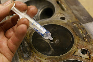
The original compression ratio was 8:1 and I would prefer something between 8.5 and 9.0 but I need to know if the head and block have been previously skimmed, so knowing the current actual ratio is essential. A little research on google comes up with a process which involves measuring the volume of the cylinder head chamber using very cold ?? liquid paraffin and a syringe. (The lady in the chemists clearly didn’t accept my explanation when she helpfully enquired as to the intended application of these items) Also included in the calculation are the swept volume, gasket thickness, piston at TDC to deck measurement and volume of the piston dome. Only the piston dome calculation (volume of part of a sphere) complicates things but I get there in the end. Chamber volume averages out at 0.016 Litres (6.469 Cubic Inches) After transferring the calculations to a spread sheet, and a little creative manipulation, miraculously it averages out between all cylinders at 8:1
Calculations show around plus / minus one percent difference
in compression ratio between cylinders. Does this matter?
I have absolutely no idea - Any comments appreciated.
It always amazes me how simply warming pistons in a bucket of hot water expands them enough for the gudgeon pin to easily punch out. More with an eye on protecting my new forged pistons when I need to re-assemble, it seemed like a good idea knock up a simple wooden jig to sit them in. If you’re wondering, the metal contraption adjacent is part of an old machine press tool and just comes in handy.
 |
| Engine broken down entirely into its comonent parts |
With some more help from Dan I have produced what I hope is a fairly comprehensive list of work for the machine shop and email this to a few likely candidates. They’ll probably read it and think – now this lad looks like trouble!
Block
Bores currently +15
Chemical / vat clean
Crack test deck surface
Check alignment of main bearings and hone as required
Fit new liner to No 3 (small “ding” in cylinder wall)
Bore to Circa +30 and hone to match individual pistons supplied
Skim deck
Con Rods
Crack test
Check for alignment
Re-Size & Re-bush
Crank Shaft
Existing – Mains are standard. Big Ends are -10
Remove plugs
Clean
Crack test
Machine to correct Main and big end bearing clearances most likely -10 and -20
Balance with Flywheel, clutch and pressure plate
Head
Weld up “cruddy” water ways and machine
Pressure Test
Replace Valve seats and cut as req.
Replace Valve guides and set stem to guide clearance
Skim
Allow for full recording / documenting of all measurements / outcomes.
Initial costing to be based on all parts to be free issued by me
Crankshaft rear oil seal conversion – exact spec requirements TBC


