Monday, 18 March 2013

POST 51 - MARCH 2013 - SCREEN WIPERS

Although my official retirement date was the end of December last year, the reality of retirement is only just starting to kick in.  I continued to help out during the transition up to the end of February but the normal pressures of business are now totally gone - forever, so it's strange to wake with the thought - what shall I do today?  This is even more the case with the car away at the trimmers

First job in the workshop is to take advantage of the space and have a sort out of parts.  A few small items have been mislaid over the past couple of months, but will hopefully appear in the process of reorganising
things.
Long overdue sort out of remaining parts

Since the beginning of this year I've deliberately avoided doing anything that can be done whilst the car is away at the trimmers, so that I would not be 'kicking my heels' for a month or so.  Consequently I have a small list of jobs lined up for the next few week, the first one being to strip and re-con the wiper motor and rack, or possibly upgrade it.


Before starting on this I did some research and looked at alternatives.  The original item has a few downsides in that it is single speed, not self parking and uses a wound field coil motor rather than the later and more powerful / efficient permanent magnet type. Will it still work after around sixty years of inaction, and if so, could it be made to operate satisfactorily in spite of its drawbacks?  With the rack removed I applied 12 volts with a 2 amp limit to avoid any disasters but nothing happened.
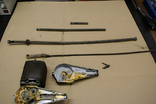
Grease is solid due to fifty years of inactivity - no wonder it wont run.

Looking at the almost solid grease in the gearbox this wasn't really surprising so the gearbox was also removed, but to no avail.  Next the end cover was removed then the brushes.  It was clear now that the output shaft was seized solid in its bearing, probably just through lack of use.

Output shaft (other end) seized solid in it's bearing

I left it to soak in a shallow bowl of thinners then turned my attention to the seriously 'gunged' up gearbox.  This was stripped, cleaned and checked for wear.  Once cleaned up, every part looked almost as good as new (as did the motor commutator and brushes).  I was quite impressed by the design detail of the gearbox, particularly the two sets of needle roller bearings supporting the intermediate gear driven by the motors worm gear.

Nicely made with two sets of 15 needle roller bearings to support intermediate gear
 
After an hour or so of soaking, the rotor shaft was free allowing the rotor to be withdrawn.  After a good clean and a coat of crackle finish paint to the motor casing, it was re-assembled and again connected to a 12 Volt supply.  This time it ran beautifully drawing just over 2 Amps without any load.  Increasing the load by slowing the worm gear drive increased the current draw by up to half an amp.  This will be a very useful way to determine the friction created by the gearbox and rack.

Motor cleaned, painted and re-assembled - as good as new

Next the gearbox was added and the current draw remained constant indicating that all was nice and free with little friction.

Gearbox added - no increase in friction


The motor with gearbox attached was left running whilst the rack and wheel boxes were stripped, cleaned and given an ample coating of Graphogen grease.  Again the wheel boxes were in exceptional, good as new condition with no perceptible wear.
The whole assembly, motor, rack and wheel boxes were now reunited.  Initially the current draw was around 0.3 Amps higher but slackening the rack retainers on the wheel boxes brought it back to around 2 Amps.  Playing with the positions of the rack outer casing ends and gradually tightening them up with the motor running seemed to allow them to settle into their preferred location and the 2 amp draw was again achieved.  After a couple of hours running, the current actually settled to 1.7 Amps (20 watts) which I would guess is about right.

Rack and wheel boxes added.  Current settles to 1.7 Amps when run in.

There seems to be an abundance of torque available at the spindles, (I can't grip them well enough to slow them down) and I can't help wondering if the bad rep the original set up suffered from was partly down to poor assembly and lubrication, generating high levels of friction.

The dash board now has the benefit of connectors so is much easier to remove which makes access to the wiper assembly straight forward.  If it transpires that they are in fact hopeless then I will have to look at upgrading.  Local fellow 120 owner Tony Hamnet wrote an excellent article in the January 2013 XK Gazette detailing everything necessary to fit a more powerful two speed, self parking arrangement.  Quite an involved bit of work not to be undertaken lightly but good to know it can be done if necessary.

Uniquely for an old car, my XK140 fixed head has excellent self parking two speed wipers, but I really miss the single wipe facility of a modern car.  In the UK it's as likely to 'drizzle' as it is to rain making a single wipe facility much more useful than a second higher speed.  So one possible side benefit of the original very basic system is that it may be possible to add a second switched supply to the motor via some sort of pulse switched timer relay allowing for a single wipe. With a mere 1.5 secs for a wipe back and forth, getting the timing right might be a problem or even impossible but it could be an interesting and cheap solution.  I'll look into it.  In the meantime it'll be fun honing the skill of switching off at exactly the right moment to neatly park the blades in the right place.

Miscellany
Trimmer John was most adamant about the need to be able to drive the car in and out of his workshop, so the run up to its delivery to him, due to this additional work, was very busy.  I had not intended to install the engine until April and bringing this forward meant not doing a few other jobs.  Consequently I was duly chastised for my lack of preparation.  As the starting procedure was complicated by the battery isolator switch and immobiliser I had written out the order of actions - Isolator on - blip immobiliser - ignition on - choke on if cold - starter button - then - choke off after a couple of minutes.   I explained all of this to John and his response was "all looks a bit complicated - I don't think I'll be bothering to move it after all".
Good trimmers are hard to find so I bit my tongue!

Next post beginning of April


Thursday, 7 March 2013

POST 50 - MARCH 2013 - ANOTHER MILESTONE

Finally got round to bringing this blog up to date, around a week late.
Its quite a coincidence that the fiftieth post should also record a bit of a landmark event, the car more or less in one piece being driven out of the workshop and onto a trailer for its trip to the trimmers at Shildon, about 25 miles away.  Never the less its been quite a hectic couple of weeks and things have been far from straight forward.  Making the car drivable took a week or so out of the time I'd allowed to prep it for trimming, so a little help was organised for a couple of days in order to achieve the deadline.  Trimmer John is a busy lad with a queue of work lined up and if I'd missed my slot, it would have made a mess of both our schedules, hence the need to get it there on time.


The biggest single problem was the attempted fitting of the windscreen pillars (which would allow the hood to be made and fitted). The original pillars were missing but I had acquired a set of three new ones and foolishly imagined it would simply be necessary to bolt them in place.  The side pillars are bolted through the bulkhead into threaded plates, again missing, so I made these up from heavy bar, and with great difficulty and much cussing fiddled them into place using a pull cord. After endless hassle I eventually had the side pillars bolted in place and offered up the windscreen glass to check for fit.

Trial fit of screen glass (without chrome surround)
 The passenger side was not too bad, but the drivers side was way out.  This initially looked like a major disaster until I realised that relatively small tweaks of the fixing points moved the pillar significantly in whichever direction required. The rearward slope for example could be easily changed by several degrees which probably accounts for the badly fitting side screens and loose hoods I've seen on several other XK's.
I do have the original side screens which are due to be re made at the trimmers, and will ultimately dictate the correct angle for the pillars, along with the glass and hood front frame, which will then dictate final position.  The upshot of this is that the hood will have to be tailor made later once the doors and sides screens are in place.
I can remember a similar problem with my Daimler Dart (SP250).   I eventually got around to fitting the hood just before I sold it.  In the preceding twenty odd years of ownership, I often used it as a daily driver which meant that my kids eight mile trip to school was spent scrunched up under the tonneau cover when it rained.

Fitting the engine back in went very smoothly and exactly as planned but did involve two hoists and three men.


The pictures above give a general idea of the sequence.  Using a pair of hoists gives very precise and easy control of the angles required to install the engine with the gearbox attached.  It was also necessary to temporarily remove the round tie bar that normally sits just in front of the radiator.

The conversion to a five speed gearbox meant that the gearbox cover would require some modification to accommodate it's slightly different dimensions.  Fortunately the gear stick is in exactly the same place so nothing too major.  Playing around with cardboard, I worked out the general shape of the extra bit, then cut this out of sheet aluminum. 

Gearbox cover mod ready for folding
Check for fit

Pop riveted in place and 'Dynamated'
Folded and pop riveted to the original, then covered with Dynamat, it's slightly different shape when fitted with a leather gaiter and carpeted and  should be hardly noticeable.

Floor and boot boards were cut out from 12mm Marine Ply, given three coats of exterior black varnish on the underside, then stained and wax polished on the top side.

The original heat shields between the silencer and floor boards were made from asbestos and one of them was missing.  As an alternative I used Duratec 750 Insulation Board which is a 6mm thick asbestos free calcium silicate plate. (RS Components Stock No 248-4630)  Expensive but very high spec, which it needs to be given that the silencer is around two inches (50mm) below the marine ply floor boards.

Aluminium extrusion with Rivnuts inserted to hold heat shield
Heat shield in place - sits about an inch above silencer!
So, with numerous other small jobs completed, oil, water and petrol were added.  The ignition and choke wiring was jury rigged and the flannelette sheets stripped off.  Then finally and unceremoniously, it was started and for the first time in fifty years moved backwards and forwards a few inches under it's own power.


Just needs doors fitting

Monday March 4th - Doors were fitted and it was driven out of the workshop and and a few hundred yards up and down the industrial estate road, but with great care as only the hand brake was functional.  Geoff arrived bang on 10.30am and it was ensconced safely in John's workshop at Shildon by 11.30.

JPEG from Geoff so small image
Next Post - Mid March   (won't be late!)

Saturday, 16 February 2013

POST 49 - FEB 2013 - NO MORE SNOOZING

The long standing appointment with trimmer John Richardson looms ever closer, with friend Geoff's trailer booked for Monday 4th March to take the car to Shildon.  Two major jobs need to be completed in the next few days, neither of which I had really planned to do at this stage.  John tells me that he needs to be able to drive the car in and out of his workshop so it needs to be operational - just.  It also dawned on me the other day, that in order to make and fit the hood (soft top), the windscreen would have to be in place - duh!
So with two weeks to go, the snoozing and socialising will have to stop.  John has already completed the dash board, seats, armrest and door panels and I would have to say that he has made a superb job of them.  The remaining work, hood, tonneau cover, cockpit rolls, side screens and carpets will be tailored specifically to the car, hence the need for it to be away at his workshop for the best part of a month.


Special dispensation given to store seats at home for a while

Exceptional job by John Richardson of Shildon County Durham
The seats in particular have worked out very well.  The bases are close to original but the backs have been changed from the slide around variety  to bucket.  This also allows for the central armrest to have an opening top with storage inside - something in very short supply in a 120 OTS.
This is an ideal place to hide the controls for the ICE kit and other occasional use switches, plus a switch to activate a small digital display showing battery voltage, to avoid fitting a voltmeter, much more use than an ammeter if the cars been fitted with an alternator.
I had some nice period switch labels engraved but couldn't resist having a second set made up for the benefit of the grand kids.  Telling grandson Freddy that he shouldn't on any account open the lid between the seats in Bobsy's 'special car' then leaving him to play should be interesting, especially when the 'countdown' LED's illuminate immediately after he's activated the eject switch.

Work in progress with alternative label for grand kids
 With the engine installation imminent, the past week has been spent fitting out the engine bay and completing any other jobs which would be harder to do with the engine in place.  The plan is to fit the engine on Sunday 17th Feb and hopefully most of the ancillary bits, exhaust system etc.  A few years back, young friend Kev Woods gave me hand to remove and re-fit the engine in my 140 when it developed an oil leak and will be on hand again to assist which will make the job a great deal easier.  Kev's day job involves maintaining heavy plant and machinery, often on site, so for him, this task should be fairly straightforward and his help invaluable.
 
Engine bay - almost ready for engine installation on 17th Feb
One item I wasn't too happy about re-using was the brake fluid reservoir - made from glass !!
Thinking about this, I realise that the early 120 master cylinder (also used on the 140) effectively has its own reservoir holding around half a pint of fluid which in turn is kept topped up by the glass one.  I can only guess that the glass reservoir was added to make it easy to check the fluid level and top it up.  In any event, it was a very satisfying part to recondition.  New rubber seals were made and fitted top and bottom and the metalwork powder coated in a colour very close to the original.  Local and ever helpful company Hawk fasteners actually had in stock the tiny rivets used to fasten the brass manufacturers plate back in place.

Master cylinder with its own half pint reservoir - ready for assembly


Glass brake fluid reservoir - scarey!

Lovely original brass plaque
Miscellany

The weather today, Saturday 16th, has taken a turn for the better, so time to disinter the 140 from it's winter slumbers.  I've run the engine and moved the car a few feet back and forth every couple of weeks, but this will be it's first run out this year.  As ever it started without any fuss and ran beautifully with all gauges indicating healthy levels of everything.
Just around the corner from my workshop is a newly re-furbished building dating from 1916.  Originally the HQ for the Cargo Fleet Iron Company which peaked in output in the 1950's and may even have made the steel used in the 140's construction.  The entrance makes an interesting backdrop for a photograph. 
Preceding this building by around fifty years, Prime Minister William Gladstone, visiting Middlesbrough's Iron Foundries in the 1860's described the town thus :
"This remarkable place, the youngest child of England's enterprise, is an infant, but if an infant, an infant Hercules"
I can't help but wonder what he would say if he could see the town in middle age.

140 after its winter break, a little dusty but otherwise superb
 Now here's an extraordinary thing.  Last year I insured my ancient Audi S4 Avant with Saga and literally halved the premium from the previous company.  (never thought I'd see Saga and S4 in the same sentence).  My Renewal Schedule arrived the other day and around the same time an invitation to renew my AA subscription.  An all singing and dancing Gold family membership, this had previously been paid by the company by recurring Direct Debit so the gradually increasing cost, this time £202.96 had not been flagged up.
Now retired with the company DD cancelled, it would from hereon be up to me. So, I had two calls to make, Saga and the AA.  Fortuitously I chose Saga first.
Answered by a UK call center, no multiple choice button punching, recorded messages and music, just a charming young man called Zack, who efficiently arranged my renewal.  He went on to pitch for breakdown cover, in conjunction with - you've guessed - the AA.  I read from my renewal document exactly what £202.96 provided and explained that was precisely what he needed to quote for, stressing each aspect, family membership etc. He absolutely confirmed it would be identical, and quoted me £37.00 yes - thirty seven pounds!  I look forward to receiving the documents to see if this can be true.

Next Post end of February

Sunday, 3 February 2013

POST 48 - FEB 2013 - LED's INDICATORS & ACCIDENTS


Determined to avoid ‘add-on’ indicators if at all possible, the only solution it would seem, is to somehow incorporate them into the existing side lights.  As we're no longer fettered by MOT requirements and with the quite recent memory of my Healey 3000’s solution of incorporating the rear indicators within the tail / brake light, this might be a possible way forward.  Some time is spent assessing the possibilities but space within both front and rear side / tail light enclosures is somewhat restricted by the existing filament bulbs.   This is easily resolved by replacing them with new LED type lamps.  Brighter and smaller, they also have a ridiculous life expectancy.  The front side light LED has an expected life of 50,000 hours (continuous for 6 years).  Assuming say 5000 miles a year at an average speed of say 50 MPH and 33% of that time with the side lights on, I'll need to think about changing them in spring - 3,528AD  !!!

LED front and rear (dual tail & brake) replacements

Now here's an interesting if slightly odd thought which has occurred to me on a number of occasions.  It would not be unreasonable to assume that this car will continue to be cherished for the foreseeable future, by me hopefully until I expire and then by countless others, but how long exactly is that.  I could quite rationally guess that it would take some catastrophic event to intervene.   This might be in the form of plague or pestilence as the bible would have it, a world war where material objects become irrelevant, or some other cataclysmic event like an asteroid strike.  All sounds very dramatic but I would imagine that at least one of the above occurring in the next fifteen hundred or so years is likely. 
It would be good to download this entire blog onto a pen drive and secrete it somewhere that I know a future restorer would find it.  Only problem is, will they be able to do anything with pen drives in 3500AD, considering that we don’t have a computer in our office now able to look at the contents of a twenty five year old 3.5” floppy disc!

Anyway, enough of this nonsense.  My discovery of LED’s to replace filament bulbs gets me thinking about indicators, but of course nothing is available for my specific application.  After a little research, it turns out that LED’s despite extreme life spans are quite fragile devices, easily destroyed by inappropriate usage.  A brief summary of their requirements would be:
They present an almost zero resistance to an unlimited current supply (a 12 Volt car battery) so must have a correctly calculated resistor value in series to limit current, typically 200 to 500 ohms depending on type, colour, forward voltage and number in series.  When you get this even slightly wrong, typically by using too low a value resistor, they go pop and produce that unique electrical burning smell, odd for something so small.  They really don’t like more than typically 20mA but some seem to be more tolerant than others.  The long leg is positive (anode). Reverse this for more than a micro second and it will probably expire.  It might be OK to connect a few in parallel with a common resistor, but this is generally considered to be a risky strategy.

So, equipped with this basic information, the task remains to physically fit enough LED’s into the space available to provide a flashing indicator of such intensity that it really cannot be missed.   Whilst both front and rear are important I reason that the rear indicators must be exceptional whilst the fronts need to just OK.

12 super bright orange / red LED's as a starting point
 For the rear, twelve super High Intensity 10,000 mcd, red to orange / red  30 degree LED’s are set into a clear acrylic housing which will sit inside the rear light lens but will allow the new LED side / brake light to show through.  (LED’s are measured in mille candela power - mcd - so I suppose each LED is equivalent to 10 candles with all light focused into a 30 degree beam)The LED’s are arranged in four sets of three. Each set of three is in series and is fed via a 470 ohm resistor.  This indicates a current flow of 20mA at 13 Volts through each set.
The acrylic housing holding the LED’s is sandwiched between the tail light glass and the metal bulb holder with a polyethylene insulator, all quite a tight fit.   

Acrylic housing with LED's - interference fit in lens
 Connected to an electronic LED type flasher unit (Max 30mA as opposed to a filament bulb bi-metal strip flasher – 10 to 200mA) it produces a very distinct orange flash of extreme intensity.  I leave it flashing for a couple of days until I feel confident that it will be reliable.  Total current for each tail light with all three functions running, side light, brake light and indicators is less than 200mA so virtually all energy is converted to light with very little heat produced.  For comparison the original filament lamps at 5 and 25 Watts for side and brake lights consumed around 2.4 Amps, 12 time the current with around 90% dissipated as heat.

Very bright and surely unmissable!
 Having found a satisfactory solution for the rear indicators, attention turned to the front.  With much less space available, the maximum number of 5mm LED's I could fit in was 5 so I may have to re-think this and see what can be achieved with the smaller 3mm variety.


Two sets in series (3 and 2) drawing between 30 and 40 mA
Not bad but I think it can be improved on
 Miscellany (not for the squeamish)
Over the past fifteen years I have produced a good many risk assessments, mainly relating to that dangerous occupation, working at height.  I thought I had a good awareness of what was likely to hurt, and given my low risk ground floor level working environment this 'accident' took me completely by surprise, culminating in the best part of an afternoon entirely wasted in A&E.  My Dewalt battery drill (which I rate as exceptional as I do most of my Dewalt tools) was sat upright on it's battery base on the bench, in hindsight a little to close to the edge, with a 3/16, longer than usual, drill bit in the chuck.  I carelessly caught it and it fell of the bench landing drill first (exactly vertical) in my left foot, having gone straight through a good leather shoe and stopping just short of the shoe sole.  Strange thing is, I have no recollection of pulling it out, only some surprise at how quickly my shoe overflowed.  An X-ray showed that the drill bit had slipped neatly between two metatarsal bones with no real damage.  Contrary to the usual H&S gurus opinions, I see no point in proffering advice for fluke accidents as I know from experience that nobody takes the slightest bit of notice.

Staged recreation of the drill through the foot incident
 I did however receive a text (one of many over the past year) offering to sue me on a no win no fee basis at absolutely no cost to myself.  These ambulance chasing 'lawyers' or whatever other dodgy profession they lay claim to, should be ashamed of themselves.  I may however take them up on the offer, just to waste their time.  Unless of course it can be proved that shoe manufacturer, Clarks are entirely to blame, disgracefully selling everyday shoes with leather so thin that it cannot withstand a puncture from a 3/16 drill with a 1.5Kg weight behind it, falling from a height 1 Mtr.

Next post mid February


Thursday, 17 January 2013

POST 47 JAN 2013 MORE ELECTRICAL

My main task for the month is to finish the electrical work which I thought would be fairly easy, but it's going rather slower than I had expected, partly due to the large number of alterations and additions.
As mentioned in a previous post, I've replaced the Lucas dynamo with a Dynalite alternator which looks almost identical.  Producing 40 amps, it is a considerable improvement on the dynamo output of 25 amps and will also start charging at a much lower RPM.  However it still falls quite a good way short of a modern car alternator at 70 to 80 amps output.  This would not normally be an issue with a fifties car, but given the amount of junk I've added I need to be aware of it's limitations.
Take for example, theoretical power requirements on a very cold and wet night - Essentials first :

Head Lights - Halogen - 2 @ 65 Watt       11.0 Amps
Side Lights 4 @ 5 Watts                          1.7 Amps
Wipers                                                    3.3 Amps
Water Pump (Electric)                             10.0 Amps
Heater Blower (Max)                                8.0 Amps
Heater Matrix Pump (Max)                       1.3 Amps

Total circa 35 Amps based on 12 Volts (31 Amps at 13.5 Volts).

Add in 8 Amps for the radiator cooling fan (unlikely, but possible if stuck in traffic) and we are on, or possibly over the edge. With 80 amp hours of fully charged battery capacity and an 'off' switch for the heater fan, not really a worry, but not a good idea to turn on the spot lights, another 7.5 Amps.  The music system (at full whack a potentially massive 20 plus amps) is definitely out. Other odds and ends like phone charger, instrument and map reading lights (or sat-nav) are negligible, but it all adds up.

All of the push in type bullet connectors which are the source of endless problems after a year or two are being replaced with fully soldered joints.  Other terminations used are screw type terminal blocks in enclosures and modern high quality multi-way connectors to connect the dash-board, the small ancillary switch panel for indicators / spot light switches, and the switches and other bits hidden away in the central arm rest.  The plan to ensure none of the additions are visible seems likely to be realised.


Common but reliable termination block for lights and indicators.

With lid in place, enclosure is IP66 rated

Multi-way connectors make dashboard removal easy.

One wiring job I've not been looking forward to is the mess of cables and connections around the Voltage control box.  In addition to the very stiff and awkward original looms there are another twenty odd cables (immobiliser, indicators and new hidden fuse box feeds in and out, of varying gauge) which need to be terminated but all out of sight.  The key to a reliable termination for the RF95 control box and other screw down terminals is having unstressed cables which don't rely on the screw to hold them in place but sit naturally where they need to be.  It takes a good deal of time and some stripping back of the original looms outer cotton covering to achieve this. Even with the utmost time and care, I would have to say this is not a happy arrangement.

Only the original wiring on show
 Back in the early ninety's car theft in the North East of England was endemic, with joy riders stealing anything that was not reasonably protected from theft.  After-market car alarms and immobilisers were big business but their design and installation often left a great deal to be desired.  Trac Communications designed and manufactured one of the better products using a newly developed fob which transmitted a code into a receptor and then to a processor which in turn opened or closed a couple of relays usually feeding ignition and fuel pump circuits.  Certainly possible to work around by a clever lad with plenty of time and a good knowledge auto electrics,but sophisticated enough to stop 99.99% of half wit twoc'ers.  The product was picked up by the UK's biggest car security and  immobiliser company at that time.  Trac manufactured them on their behalf and did very well out of it.  Eventually it became the norm for manufacturers to fit their own devices to all new cars and production ceased, but a small stock of a few hundred were retained as spares / replacements but never used. Since then I've fitted one to every classic I have owned and given quite a few to other classic owners.  100% reliable, they will certainly stop an opportunist thief which is probably the most likely sort to nick your classic.  Needless to say, one is secreted within the innermost depths of the 120 with its confusingly identical mass of black unmarked cables.

Trac Immobiliser - at the cutting edge of theft prevention in the ninety's.
Miscellany

Slightly fanciful, but I came across this image by accident and couldn't help noticing the similarity in shape.


Next Post early February

Saturday, 5 January 2013

POST 46 - JAN 2013 - ELECTRICAL SYSTEMS

This part of the restoration is most closely related to my daytime job as a Communal TV systems Engineer.  Much easier in some ways because I'm simply dealing with 12 Volts rather than the losses and gains of various cables, amplifiers, switches etc. all at varying frequencies.

Batteries
The starting point for any automotive system has to be the battery and I have chosen to retain the original location but use two 12 volt batteries in parallel rather than two six volt in series.  Two advantages - a saving of around £100.00 and a gain of 30 Ampere Hours.  As long as they are the same and ideally both new and connected with very short fat cables, the problems associated with batteries in parallel will not be an issue. I purchased two Type 202 (the same number is used by most manufactures, Lucas, Varta etc.) rated at 40Amps and 350Amps Cold Cranking which when doubled should be very adequate for a 3.4 motor.  They sit a little lower than the original batteries but amazingly, the retaining bars are a perfect fit

One of the type 202 batteries in the original location - a perfect fit!

Ancillary Systems
The list of additional and upgraded electrical items, I will readily admit, has got out of hand, but reviewing it, there is nothing I want to omit so I just need to get a handle on it.  Having spent many hours over the years producing schematics and circuit diagrams, it's second nature to draw up exactly what I require.
It's an interesting exercise and and I should point out that it is still a work in progress but is now pretty close to how it will finish up


Circuit diagram for additions and upgrades
All still needs validating, but won't be far out.
Ancillary wiring harness
Rather than add wiring on an ad-hock basis, I made up an additional wiring harness incorporating every additional cable, and all to be kept out of sight.  This was eventually achieved by laying out the complete set of cables on the floor and first wrapping them in PVC loom tape, then cotton tape which looks very original.
Part of ancillary loom runs through sill with original loom


Alternator / Ammeter mods
One slightly tricky area to address is the problem of modifying the charging and power circuits to accommodate an alternator and still have the ammeter register both charge and discharge.  For obvious reasons, the starter motor feed is far too heavy to pass through the ammeter.  This in turn means that an additional heavy terminal is required for all power requirements except the starter motor.  However, if a gear reduction starter with internal solenoid is used, this effectively frees up the second heavy terminal on the original solenoid which is ideal for this purpose and is also in exactly the right place.


Note - Direct feed to fuse box is not routed through the ammeter
to minimise voltage drop to Halogen lights - see below


It is of course necessary to disable the solenoid and I achieved this by simply drilling a small hole through the hand operated 'plunger' and fitting a split pin.  The solenoid's starter terminal is also redundant because the feed from the starter button now goes directly to the new starter motor.


Solenoid - Cleaned up and manual operation disabled with
a split pin through the end of the 'plunger'

Halogen Headlights and relays
The next upgrade to deal with is the wiring requirements for halogen head lights.  Optimum performance is only achieved if they are served by their full design voltage (typically 12.8V) and light output diminishes by a factor of 3 with a reduction in that voltage.  For example, a 10% reduction from say 12.5 Volts to 11.25 Volts will reduce brightness by around 30%. (from approx 1,500 lumens to 1,050 lumens for a 65 watt rated main beam filament) which is probably only slightly better than a new original tungsten bulb.
The 120 power supply to the lights takes a fairly circuitous route from the battery.  Through the ammeter, then the voltage controller, light switch, dipper switch, fuse box and various nasty interference fit connectors, so the potential for high resistance and subsequent voltage drop is pretty good  (I would not be at all surprised to see one to two volts disappear on route).


Relays located in headlamp pods
My solution (hopefully), is to use the original wiring to switch a relay located close to to the headlights and fed by a heavy (27 Amp) wire direct from the battery feed terminal on the solenoid.  This should pretty well ensure that the halogen lamps are always fed by something closer to the full battery voltage, or even the slightly higher alternator output voltage.  Taking this feed through the ammeter again would rather defeat the purpose, so I just need to be aware that the headlights will not register a discharge.  Strictly speaking, conversion to an alternator means that the ammeter is now semi redundant anyway, and a discreetly placed volt meter will give a better indication of system performance and health if required.

Relays and heavy feed cable should give 50% more light


All of the above have been tried and tested in previous projects, but that doesn't mean that there is not an error in the drawings at this stage.  Only when the  it's all up and running will I be confident enough to suggest that it's 100% correct.

Miscellany
This post should have appeared around the 2nd of January but a series of events prevented that happening and subsequently caused me a great deal of hassle.  It started with me being unable to add pictures to this blog on my PC at home using the Internet Explorer browser.   I could however add them using an office PC which used Firefox.  I attempted to download Firefox onto my home PC but in spite of all manner of Anti-Virus Software it was quite literally Hi-Jacked / redirected by a nasty bug browser called MyStart by Incredibar, apparently a product of Perion Networks Ltd.  Reverting to Internet Explorer, 'incredibly' it had replaced that also, but did not appear anywhere in my lists of programs when I looked for it to remove.  This rubbish browser with endless pop up adds also suffered from the same issue re. adding pictures to this blog, presumably due to some change made by Google.  Consequently, on my home PC I seemed to be stuck with it.  These people at Perion are obviously very clever to be able to do this, but also incredibly stupid to allow this to sully their reputation (assuming they have one of course).  Not as stupid however, as the companies who presumably pay to advertise (or do they?) and by association will be universally despised along with Perion.  Ironically, using their browser I find a mass of posts all relating to this issue and all very cross.  Perion appear to be an organisation of some substance.  If they are in fact linked to My Start and can only get their products onto your PC by the use of malware, then I fear for their future - or am I being naive because this is the future?
One of our clever lads at work found and removed the horror without too much trouble so things are back to normal (unless MyStart Inrcedibar / Perion Networks Ltd knows better!).  I do take some comfort from knowing that approaching 5,000 people (assuming Googles Stats are to be believed) will have read this by the end of January

Next post Mid January