Wednesday, 15 August 2012

POST 36 AUGUST 2012 IGNITION SYSTEM & USB PROGRAMMABLE DISTRIBUTOR

By the end of this month that scary engine start up moment will be imminent with only the exhaust system, cooling and ignition left to fit.


In close to fifty years of driving old cars, I would say that nine out of ten problems I've encountered on the road have been electrical and often ignition related.  Back in the sixties, even brand new cars had problems, especially on cold wet mornings when they were reluctant to start.
With this in mind, I'm keen to ensure that my electrical and ignition installation will never give me cause for concern.  It would also be good to see a pristine 1950 engine bay.  This competing requirement will inevitably result in some compromises, but original HT leads and plug caps would be good.  The downside might be interference to my proposed DAB radio installation, electro magnetic interference upsetting my electronic ignition system or RF noise locking up my neighbour's digital TV's as I pass by.  I really don't know and can't find any one that does, so it will be a case of try it and see.  Fortunately I have access at work to a Spectrum Analyser which will display whatever nasty stuff is being radiated and provide precise data relating to the effect on digital radio and television signals.  I'll let you know the outcome.
Cap, conduit and HT leads not quite as original and needing
some attention
XK's for the first few years had the HT leads routed under the carburettors and around the back of the engine leaving the front uncluttered.  It was not until 1953 that they were routed over the cam cover, possibly for some technical reason or maybe just to save a few pence on a couple of yards of HT cable.  Again, no one seems to know.  As a very early 120 my car would have benefited from that original design and in the absence of any good reason to revert to the later layout I adopt the original route.  To minimise the possibility of cross firing between leads (one of several reasons mooted for the change) I run them in an aluminium tube with a central polypropylene rod and original Bakelite spacers to keep them separated.  The tube is heat insulated from the engine with a calcium silicate sheet.
Original HT lead conduit cleaned up beautifully with black
boot polish.  Note polyprop rod to keep leads separated.

Neat solution to route leads under carbs

Note red 'Champion' labels on plug caps.  Not sure if they should be there. 
Definitive answer for a December 1950 car anyone? 
To improve on the usual practise of simply relying on strands of wire pushed into retainers to make electrical connections, the HT lead copper conductor is carefully splayed within the brass connector to the distributor cap and soldered in place.

Centre copper conductors splayed and soldered to brass connector
Next consideration is the distributor.  I have over the years had many a disagreement with the Lucas unit in its various forms and as its not particularly prominent within the engine bay, it will have a modern replacement.  I fitted a 123 Ignition distributor to my Frogeye around three years back and have never touched it since.  The very latest version is the 123 Tune with a USB port to connect to a Lap Top and programme in whatever curves you want.

Superbly engineered 123 Ignition 'Tune' distributor with USB
 port to programme your choice of advance curves.

The software to run this is downloaded from :  http://www.123ignition.nl/downloads/software/123Tune/ 

Running the programme, the first screen displays a very comprehensive dashboard with clocks for RPM / Crankshaft advance, Coil current, Distributor temperature, Vacuum and a timer to compare acceleration between two pre-set RPM points.


The second screen allows you to select seven points of crankshaft advance and seven points of vacuum advance / retard.  Each series once selected can be saved to file.  The distributor is connected via a USB lead and two 'curves' selected and downloaded into it.  It is possible to switch between them by applying 12V or 0v to the distributor's yellow lead.


The XK workshop manual has sufficient information to allow you to emulate the original setting for the Lucas distributor or you can put in your own.  You can even play about with them on the road, using the timer to compare acceleration between settings, but only after confirming that you are a passenger and not the driver, a neat touch.  If you happen to have access to a rolling road and dynanometer then you could really have some fun.
I had the benefit of following on from friend Tony Hamnett who fitted one to his 120 a while back and emailed me a whole series of curves taken mostly from the 123 Ignition website and tweaked for his particular application.  I simply selected the two he found best, imported them and downloaded them into the distributor.
My most likely application for the two settings, given the shortage of 99 Octane in this part of the County of Yorkshire (12th in the Olympics Medal table or top by a very long mile on a population / medal basis) would be to switch between curves optimised for high and low octane fuel.

Heat shrink nicely finishes of caps and will keep moisture out
On the recommendation of a couple of respected enthusiasts, I fitted a set of Iridium needle point plugs to my 140 about eighteen months / 7000 miles back and its run like a sewing machine ever since.  They are quite expensive at around a tenner each, but so far show no signs of wear so they're naturally included in the 120 spec.

Iridium needle point plugs - probably the best present an XK could have

From an appearance stand point, the end result is just about as good
 as I had hoped for
So that pretty well ties up the ignition system, all done with great care and attention, and I have absolutely no doubt that when I switch on the ignition and press the starter button for the first time - it won't start!


Miscellany
Autobodycraft, the company doing the 120 body, staged their own charity Motor Show on Sunday 12th August.  More than 100 vehicles were on display, 1500 people attended and over £5,000 was raised.

Great example of Yorkshire humour

Rat car with monster truck turbo diesel
Next Post beginning of September


Monday, 6 August 2012

POST 35 AUGUST 2012 NO MORE BOOT LID BLUES

The saga of the boot lid could fill a couple of books all by itself.  To recall.
It was missing along with many other parts when I bought the car back in 2010.  I did eventually acquire one which had had the bottom third of the ash frame replaced, but when offered up to the car, the overall shape was wrong.  I returned it to the supplier along with profiles cut from hardboard showing the exact shape required.  It was duly reworked and returned and a trial fit confirmed that it was now fairly close to being right.
However, close inspection (a little late in the day I will admit) showed that the aluminium skin was secured to the frame in many places by steel nails. Body shop man Alex was less than happy with this and I was sent packing yet again, booted out, boot lid in boot so to speak to find a solution.
Lid No 1    Less than ideal skin, lots of holes and a few nails.
 I allocated a whole day to resolve this and played around carefully removing the steel nails and replacing them with specially made (by me) aluminium pins bonded into the ash with the intention of welding the heads to the skin. After several hours of prating about, it became very clear that I was pissing in the wind (I apologise for the language but it best describes the mood) and went home.
The following day, a Sunday morning I am back with renewed spirit, take afresh look at mess I've made and decide to do something else instead. 
Contemplating the purchase of a complete new lid at circa £3000, I recall a conversation I had about a year back. A friend of a friend said he may have one but it was probably beyond repair. A couple of phone calls and an hour later I'm in the garage of Rob Hind at Sadberge and looking at a rotten wood frame with perfectly good skin.
If I can fit this good skin to my OK-ish frame that might be be the answer.
Lid No 1    As well as repaired bottom frame, steel strips are rusting
Back at the workshop and further investigation indicates that opening up the wrapped around edges of the skin will be difficult.  I try annealing first but can tell that anything more than slightly opening the seam will end in tears.
I eventually manage to remove the rotten frame from the skin and and determine that it should not be beyond my wood crafting skills to fabricate a whole new frame to fit into it rather than use the repaired one.  This massive misjudgement is dealt with in detail in post 29 (Boot Lid abandoned). 
As outlined in this post, after many hours of wood wasting, I eventually find and order up an exact copy of the original frame for £250.  As requested, it is delivered in pieces enabling me to build it into the skin.  I am now back in my comfort zone and work proceeds apace making up new steel strips to screw onto the frame and slip into the aluminium skin.  The frame is temporarily built up with hinges, handle and catches and a trial fit looks promising.

First trial fit of temporarily assembled boot lid frame looks good
Next I need the aluminium trim pieces to fit around the edges and Contour Autocraft come up trumps again with a really good fitting set.
Having established that the frame is fundamentally the correct shape I prime and refit the steel strips, inject Tiger Seal into the folds then assemble the frame into the skin.  Crimping the skin back in place with a special tool borrowed from Alex was very easy, but the addition of the sealant means almost certainly that it will never come apart again. 

Edge crimped onto steel strip and sealed in with Tiger Seal

Ash and softwood laminated frame match the rear end shape exactly

Back to the body shop and Alex tweaks the fit, bashes it around a bit then skims and shapes it before giving it back to me.  All that's left is for me to glue it all together and fit the corner pieces supplied with the frame kit.  Its finally taken back to Alex who is at last satisfied that once painted, it will look perfect and more importantly stay looking perfect.  My final job will be to fit the inner plywood panel but this will be done from underneath with the boot lid fitted, to ensure that no twist occurs. 

Rare view of boot lid from petrol tank location.  Ply panel will
be fitted from here to ensure no twist occurs.
Once screwed in place this adds an unbelievable amount of stiffness to the whole boot lid structure.
Just for fun I tap into our companies small works costing programme for jobs based on time and materials.  I put in my time spent, material costs and associated travelling - three time to Newcastle and twice to Harrogate.  With an hourly rate of £37.60 a nominal overhead cost and mark up it totals up to £3,267.27  There is a moral in there somewhere. 

Miscellany - related topics

Croft Nostalgia Weekend
Preceding the Croft Classic Weekend I was invited to a Press Day along with a few other JDC members to help promote the event.  It turned out to be a thoroughly enjoyable day with plenty of opportunity for track action and quite well organised compared to last year.  BBC regional News gave it a half minute plug in the evening and my 140 appeared for a nano-second at the back of a bunch of cars on the track and a few seconds later at the front - if only!

The Croft Nostalgia event is a fabulous weekend with all the atmosphere and a good deal of the spectacle of the Goodwood Revival, but without the huge crowds. The BRDC have a full programme of classic racing and everyone has access to all areas including the paddock. At £25 for both days its quite a bargain. No doubt it will cost a little more next year.
Set up 1955 Photo I took end of July at Croft Press day

Trailer mounted Rolls Royce Griffin V12 ticking over. Only a couple
of wheel chocks stop it shooting off down the runway when opened up.
Next Post mid August


Tuesday, 17 July 2012

POST 34 - CONVERSION TO HYDRAULIC CLUTCH - OR NOT

Hydraulic - V - Mechanical Clutch Operation
I had every intention of converting the clutch from mechanical to hydraulic operation and to that end purchased a 150 slave cylinder with mounting bracket. The bracket did not exactly fit the 120 bell housing and required a fair bit of fettling to get the push rod moving at something like the correct angles when moving the clutch operating lever. It did eventually all line up reasonably well but looked like a bodge, as if it was never meant to be there.
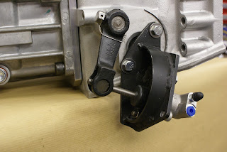
This just doesn't look right
To resolve the master cylinder issue, I had considered fitting a complete new pedal box but at 5 foot 8 inches tall, and with bucket seats fitted, the original pedal location, for me, should be just about right.  The current trend to move the pedals forward a couple of inches, which a new pedal box would allow, might increase the cars future saleability.  (I remember reading somewhere that tall men are generally richer than short men).  Having to put blocks on the pedals as my dad did on my first bike seems like a naff idea, and I am after all building this car for me. 
So, having acquired a likely master cylinder some time back, I set about looking at how to best utilise it in conjunction with the existing pedal arrangement.  With the new slave cylinder fitted, there is no longer a place for the end of the clutch operating shaft.  This can possibly be resolved by making up a substantial plate with some form of bearing for the remote end of the cut down shaft.  Also, the operating lever will need to be relocated with a new key way machined into the shaft and the chassis will need some holes drilled to attach the plate.  It's all getting horribly complicated.

Time to ask the obvious question.

Why exactly do I want to operate the clutch hydraulically?
Whilst the mechanical arrangement has lots of parts, it is in fact reassuringly simple with very little if anything that could fail catastrophically. 

As usual with Jaguar design, many parts make up the clutch
operating mechanism.  Note washer in bottom right hand
corner and see "whats that clicking noise" below.
My 140 has exactly the same arrangement and I have never thought it heavy to operate.  With a 9.5 inch E Type pressure plate it will be lighter anyway.  No seals to worry about and no hoses to split.  Nothing to bleed and no fluid to periodically check and top up and wonder where it went.  On the other hand, the idea of having a shaft mounted between one fixed point, the chassis, and one vibrating point, the engine, can not in principle be good.

Very odd ware characteristics on end of clutch shaft, bearing and cup.
Looking at the wear patterns on the bell housing end of the shaft, spherical bronze bearing and cup, it clearly has not had a happy life.  Never the less, it was still working (as far as I could tell) after fifteen years of hard use and neglect and a further forty five years of miserable lonely inactivity.
On balance, it's clear that the right and proper thing to do is to restore it to its original mechanical state, rotating happily in new bronze bushes, carefully lapped into their cups and then lubricated with very best grease that money can buy.    Why did I ever think it a good scheme to usurp this fine piece of engineering with masters, slaves and their vile corrosive hydraulic fluid.  Whilst on a roll so to speak, perhaps I should consider upgrading the braking system with cables, rods and levers!
My good friend Richard Cook who fortunately understands my passion for such things, machines the badly worn end of the shaft and fits a sleeve making it as good as new.  Medical science has some catching up to do.

Resplendent with new sleeve, bush and cup.  What more could
an original clutch operating shaft want?

So I guess the only remaining question is :
Is there anyone out there who would like to buy a brand new Tilton 74-700  7/10" Master cylinder kit complete with remote mounting kit, hoses and clips and an XK150 slave cylinder with slightly butchered mounting bracket.

Mr Happy Shaft back home and back in employment.

Tilton Master Cylinder - Heading for EBay

Whats that clicking noise?
Pushing the clutch pedal on my 140 would often but not always produce a light clicking noise which could be felt through the pedal. As it came and went, I was never too concerned.  Last winter I decided to investigate and removed the whole clutch shaft assembly, cleaned it, replaced the bearings, "O" rings etc. and re-assembled it. The result was a satisfying silence. The noise had gone, for about a week, then it re-appeared. With assistance and a listening tube, I established that the noise emanated from inside the chassis. The end of the spring had worn and worked its way into the chassis side, sometimes catching and winding up then twanging free with the shaft motion. It seemed strange that nothing was fitted to the shaft to stop this happening.  About this time I bought Bernard Viarts amazing book - Jaguar XK140 Explored.
Bernard Viarts amazing book on the 140 and a typical drawing.
A 120 edition is hopefully due out later this year

The superb drawing of the clutch shaft assembly, although for a left hand drive car, shows a washer (C3295) between the spring and the chassis.  Definitely not present on my car and very unhelpfully not shown on plate F of my Jaguar parts manual.  I found a suitable washer and did a trial fit.  Removing the shaft to fit the woodruff keys, the washer fell off the end and into the chassis.  My 'magnet on a stick' fished around inside the chassis and was carefully removed with not one, but two washers attached!   It doesn't matter which way you remove the shaft, the washer will most likely fall off into the chassis.  Consequently, you would never know it was ever there, and the parts manual nicely confirms its non existence.

Prop Shaft angle
The new prop shaft to fit the T5 box finally arrived and was fitted, but the angles required by the UJ's to meet the diff seemed a bit severe. The reason of course was that the re-tempered springs are sitting high with very little weight to settle them. I calculate that a full fuel tank, rear part of the body with boot contents and the best part of two passengers would approximate to 200Kg's.
Fortunately I have to hand a pallet of coaxial cable with each 250 Mtr reel weighing about 11Kg. Stacking 18 reels over the axle settles the springs very nicely and makes the prop shaft angles acceptable.
18 reels of coaxial cable approximately equates to the back half
of the body, a full tank of fuel and a couple of big lads.
Springs and prop shaft angle now look about right

Cylinder Head and Gasket - Final solution
Following on from my previous post and the problem of fitting the camshaft sprockets, assuming my calculations are correct, it looks like I will have to settle for a thinner gasket and a compression ratio of 9:1.   Rob Beere supplied another Cometic composite gasket, this time 60 thou, and it all goes back together without a hitch.

Sprockets fit easily to cams with gasket reduced to 60 thou.
Why has the head got this odd double stamped engine number?
See post 10 for the most probable explanation.
It's still a puzzle as to why, with only 18 thou being skimmed of the head the chamber volume was reduced by around 10%.  One possible explanation could be the depth of the new valve seats and the profile of the valve top, but I don't have another head to compare.  Another explanation could just be that my calculations are rubbish.

Could valve seat depth and profile be responsible to reduced chamber volume?
As I intend to use a 123 Ignition set up with programmable advance curves via USB port and lap top, I am hoping that this is all a bit less critical and I will have the opportunity to tweak the timing to accommodate the higher ratio. With 99 octane costing around £1.40 a litre (that's around $8.30 a US Gallon to you hard done by American boys) and not available at many petrol stations, you can see why it would be good to be able to use 95 octane.  I know that the theory says 99 gives you a bigger bang so you should use less of it, but in my experience it seems to make little if any difference.

Miscellany - related topics

Beamish Rally
A couple of weeks after this wonderful day out, I received a phone call from Mr George Jolly, the event organiser to tell me I came first out of around 150 entrants.  Totally unaccustomed to winning anything ever, this came as very nice surprise.  However, the actual credit for the win must go to navigator Tony Firth, who has an encyclopedic knowledge and recall of all things relating to old motors, no doubt giving us a super high score for the quiz part of the rally. 

Stuffed again by the weather men.
The biggest classic car event in North East England at Newby Hall near Ripon was cancelled after a "pitch inspection" four days prior to the event.  No doubt the forecast of a further twenty odd hours of heavy rain over the next three days would have played some part in the decision.  Apart from the occasional light shower on Friday, the forecast was around 95% wrong.

Next Post beginning of August


Monday, 2 July 2012

POST 33 - JULY 2012 - PROGRESS 1 - FUN 5

Cylinder Head, Compression Ratios and Gasket Choice
After a few hiccups relating to shims, I finally feel happy with my cylinder head assembly.  The waterways have been welded up and re-machined with 18 thou skimmed off to clean it up.  Inlet and exhaust faces have had a light skim to ensure absolute flatness.  New hardened seats and phosphor bronze guides have been fitted along with stainless steel valves and new springs.  The camshafts were in excellent order and just needed a light clean up and new bearings.  So all in all, a pretty comprehensive head overhall.
Time to decide on the ideal compression ratio and consequent gasket thickness, with a wide range available, from the original 15 thou, all the way up to special order composite items at 130 thou.  First I need to re-establish head chamber volume after machining.  I did this exercise previously by using liquid paraffin, establishing its specific gravity and weighing it on letter scales.  All chambers came out at between 105 and 107cc which I thought a little high but surprisingly the C/R came out about correct at 8:1 on my spread sheet.
This time I did the same exersise using a 100cc burette and water (as I subsequently discovered that the SG of liquid paraffin is not absolute) and they came out at around 95cc. 

No more make shift measuring.  A proper burette and a clear DVD
stuck down with a smear of grease.  The head was first set exactly
level to avoid surface tension bubbles under the plastic.

To acheive my ideal 8.5:1 C/R my spread sheet indicated that I required a gasket of around 90 thou and Rob Beere racing had a Cometic 98 thou composite item in stock.
Delivered the following day it was fitted and the head duly torque'd down to 60 foot pounds 

PROBLEM

No matter how hard I tried, and how carefully I positioned the tensioner, one or the other sprockets would not go over the end of the camshaft indicating too thick a gasket or too short a chain.   I had, as a matter of course previously checked the chain length against the original with no discernable difference.  The shortfall was nothing more than at most a frustrating millimeter or so, indicating a gasket thickness reduction of half that (as the chain goes around two sprockets) - around 20 thou.  Again consulting my spread sheet, going down to 60 thou would produce a C/R of just over 9:1 not my absolute ideal but easily acceptable.
More on the final outcome in my next post.

Dynalite - an alternator that looks like a dynamo
I spent quite a while researching this and finally concluded that it was a worthwhile upgrade, producing a maximum of 40 amps and wieghing 10 pounds (the original Dynamo wieghs 19).   The alternative was to buy the bracket and pulley plus a cheap scrap-yard alternator.  It would doubtless have saved a considerable sum but the essential pulley only comes as part of an upgrade kit, with no supplier prepared to sell it on its own. 
The dimensions of the Dynalite are identical to the dynamo and I added the finishing touch by fixing the original  "Lucas Special Equipment" plate and faux rivets to the body.


Adding the Lucas plate has probably voided the guarantee!

Morgans Diary
Anyone wanting to know what's happening on the Classic Car scene in the North of England buys Morgans Diary in February, which lists pretty comprehensively every event for the year.  It's also used by organisers to avoid clashes with other events.  So how did this super useful publication come about?
Many years ago before the internet, Mr Morgan started to keep a list of dates for Classic Car events, Auto-jumbles etc. in the North of England and word got around that he was the man to ask if you were planning an event or looking for something to do at the weekend.  After a while he formalised his lists into a small printed publication and sold copies, with the proceeds going to charity - Good Bloke. 
It's popularity grew to the point where it was almost a full time job for a single individual and Mr Morgan decided he had done his bit and it was time for someone else to take up the reins.
Step up to the plate Tony Raylor and York Vikings Rotary Club - with many volunteer hands to make light work of the job.  Morgans Diary (Now officially called Morgans Guide to Historic and Classic Vehicle Events) has raised to date an amazing £150,000 for charity and recently handed over £10,000 to The Great North Air Ambulance.
For a publicity shot they needed an appropriate Classic car as a link and as I had the time and live reasonably close to Tees valley Airport I was both happy and honoured to oblige.

Rotary Chairman Martin Kirby hands over a Cheque for £10,000
to Great North Air Ambulance Paramedic Dave Allanby

Raby Castle - JDC Area 11
The lack of overall progress in the past two weeks has mainly been down to a very busy schedule of shows and trips with no work taking place over any weekends in June.
June 24th was JDC Area 11's main annual event at Raby Castle.  As an added attraction we decided to take my rolling chassis along.  It created a huge amount of interest and it was gratifying to hear dads explaining to their kids the purpose and function of the various parts, normally covered up.

120 Rolling Chassis on display at Raby Castle  June 24th
Also on display were a couple of couple of cars borrowed from Jaguar Heritage and used in films,
the Mike Myres Union Flag painted "Shaguar" and an XK8 from the Bond Movie, Die Another Day, with a Gatling type gun mounted on the back.


Couldn't miss this photo opportunity
As I wasn't going to get the chassis back until the following Wednesday I took the opportunity to freshen up my workshop and give the floor a coat of paint.


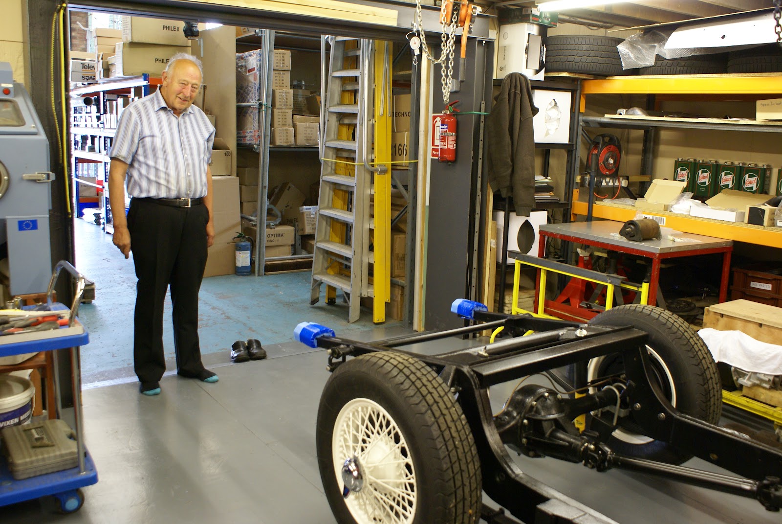
Mr G M wisely removed his shoes before entering.

Safely back home.  Shame about the sheep Sh--- in the tyre treads
The following Saturday JDC organised a visit to the North Yorks Moors Railway Workshops at Grosmont which involved a drive through some of Englands most deserted roads, with fantastic moorland views.   Just as well I forgot to take my camera.  This post would otherwise be never ending with pictures of hills and Steam Trains.

Hob Hole near Westerdale - Superb "exactly as shot" composition
 by Geoff Mansfield with only a few seconds to set up.

Next post mid July


Monday, 18 June 2012

POST 32 - JUNE 2012 - Chassis Mod to accommodate T5 Box

Spigot bush 
Splitting the engine and gearbox after the trial fit, I notice that the assembly grease on the end of the gearbox main shaft is only displaced around 15mm.   This explains why they supplied a new spigot bush (yet to be fitted) with the T5 box.  Fellow XK enthusiast Tony Hamnet explains - the T5 main shaft is slightly shorter than the Moss item and is also moved back 10mm by the box to bell housing conversion plate.  The new bush effectively extends the bearing surface forward by around 15mm.
New Spigot Bush extends bearing surface forwards around 15mm.
Re. my previous post and the question - what is the purpose of the T5 box additional cables and socket.  Dan at Classic Jaguar tells me they are connected to an internal switch which is only closed in the neutral position.  If placed in series with the starter solenoid feed, it means that the car cannot be started in gear. 

Modifying the chassis to accept the T5 Gearbox
With the engine bottom half and gearbox now permanently together, I suspend them over the chassis with the front engine mounts vertically aligned in order to establish what needs to be done to accommodate the gearbox rear mounting pad. 
Hate to change the chassis cross member but will no doubt consider
it worthwhile when snicking through the T5 box next summer.
The existing mounting plate needs to be removed and the vertical support plates cut back to around 35mm.  A section 8.5" wide, 30mm in and 50mm deep at the sides is the removed from the top front edge of the cross member.  I also take out a small "V" top centre to allow for the gearbox central web.

Section cut out ready to take new metal.
I really must give those shoes a polish.
Next I make up the gearbox support plate.  This is very simply two lengths of 2mm thick angle.  The top piece to fill the hole is 50/50mm by 8.5" with the vertical section cut to match the shape of the cross member, plus the "V" for the web.  The bottom piece is 35/35mm by 8.0" and will fit between the remains of the vertical supports and provide additional strength. 

Apologies for the measurement mixture but as an imperial boy and a metric man it works for me.
Simple to make but very strong - filler and support

I can't believe this is a casting error so can someone tell me
why the mounting plate is around 10 degrees from horizontal?
Another intriguing anomaly is that the gearbox mounting is at an angle of 10 degrees from horizontal. As American muscle cars use symmetrical V8's, this seems very strange. It also means that the nearside bobbin needs to be 13mm higher than the offside. Getting this right was very time consuming.

Bobbins set to allow for angle with tapered washers.  Note essential
extra long threads on bobbins to clear 15mm thick mounting.

Neatly welded in place (not by me!) with 2mm plate filling in
the sides.  Fine texture stone-guard and two pack satin finish
all made good.

Finally in place.  Output shaft centre is 2" above top of cross
member as per original moss box .
In some ways this turned out to be more straightforward than I expected but did take some time to get exactly right.  The mounting is very strong especially with the bottom piece of angle welded to the front face of the chassis cross member.   This will hopefully be helpful for others in the future.

Classics on show Stokesley - June 16th
My home town held its first Classic Car Show on Saturday 16th June, organised by the local Rotarians.  In spite of a rather poor weather forecast, a turnout of over 100 classics enjoyed an extremely good atmosphere with many old friends meeting up and enjoying the day.

A corner of the large show ground swallows up the 100 plus
classics turning up to the very first Stokesley "Classics on Show"
England's Green and Pleasant Land at its best.
Almost all Classic shows in the UK are held in fairly isolated locations in the grounds of Castles or Country houses making the participants a somewhat captive audience.   Fine for us hardcore enthusiasts, but it does understandably discourage wives and families from joining us.  This venue is a large traditional and well established English show field within a few minutes walk of a lovely old Yorkshire market town.  Interesting shops, pubs, restaurants and the picturesque River Leven offer some respite for those less involved.
Just a matter of time I think, before the list of world class venues reads - Pebble Beach,  Carmel, Amelia Island,  Stokesley, Villa d'Este,  Salon Prive'.
Congratulations and thanks to the organisers for a very enjoyable day.

Beamish Run - June 17th
'The Beamish' as it is generally known, is a 144 mile County Durham based reliability trial for vehicles manufactured before the end of 1955 (very strict).  My 140 fixed head just qualifies and is possibly the youngest of the 160 cars participating this year.  Early car manufacturers used a number of notably difficult routes, with streams to ford, long and steep gradients to ascend / descend, often with very sharp bends.  The Beamish Connects many of these trial routes together and makes for an exhilarating full days rally.  In addition to completing the course, points are also scored by answering a series of often eclectic motor related questions at each check point.  A superb day out in some of England's most beautiful countryside and loads of fun.

End of day.  XK140 and super rare Swallow Dorreti. 
Note standard British Post War Male hands in pockets stance.
XK120 came all the way from the Isle of Man

Not always green and pleasant.  I wonder how many seconds
this particular rash of wind turbines will add to the life of the earth.
As far as I know there is not a collective noun for wind turbines so
'rash' seems appropriate, as it is commonly used for unpleasant
  things that suddenly appear.
Grandsons "Chicken Pox Charlie" (left) and "The Fredster"
help with the Monday morning clean up.

Thanks Uncle Dan
http://www.classicjaguar.com/
Next Post beginning of July