Monday, 18 June 2012

POST 32 - JUNE 2012 - Chassis Mod to accommodate T5 Box

Spigot bush 
Splitting the engine and gearbox after the trial fit, I notice that the assembly grease on the end of the gearbox main shaft is only displaced around 15mm.   This explains why they supplied a new spigot bush (yet to be fitted) with the T5 box.  Fellow XK enthusiast Tony Hamnet explains - the T5 main shaft is slightly shorter than the Moss item and is also moved back 10mm by the box to bell housing conversion plate.  The new bush effectively extends the bearing surface forward by around 15mm.
New Spigot Bush extends bearing surface forwards around 15mm.
Re. my previous post and the question - what is the purpose of the T5 box additional cables and socket.  Dan at Classic Jaguar tells me they are connected to an internal switch which is only closed in the neutral position.  If placed in series with the starter solenoid feed, it means that the car cannot be started in gear. 

Modifying the chassis to accept the T5 Gearbox
With the engine bottom half and gearbox now permanently together, I suspend them over the chassis with the front engine mounts vertically aligned in order to establish what needs to be done to accommodate the gearbox rear mounting pad. 
Hate to change the chassis cross member but will no doubt consider
it worthwhile when snicking through the T5 box next summer.
The existing mounting plate needs to be removed and the vertical support plates cut back to around 35mm.  A section 8.5" wide, 30mm in and 50mm deep at the sides is the removed from the top front edge of the cross member.  I also take out a small "V" top centre to allow for the gearbox central web.

Section cut out ready to take new metal.
I really must give those shoes a polish.
Next I make up the gearbox support plate.  This is very simply two lengths of 2mm thick angle.  The top piece to fill the hole is 50/50mm by 8.5" with the vertical section cut to match the shape of the cross member, plus the "V" for the web.  The bottom piece is 35/35mm by 8.0" and will fit between the remains of the vertical supports and provide additional strength. 

Apologies for the measurement mixture but as an imperial boy and a metric man it works for me.
Simple to make but very strong - filler and support

I can't believe this is a casting error so can someone tell me
why the mounting plate is around 10 degrees from horizontal?
Another intriguing anomaly is that the gearbox mounting is at an angle of 10 degrees from horizontal. As American muscle cars use symmetrical V8's, this seems very strange. It also means that the nearside bobbin needs to be 13mm higher than the offside. Getting this right was very time consuming.

Bobbins set to allow for angle with tapered washers.  Note essential
extra long threads on bobbins to clear 15mm thick mounting.

Neatly welded in place (not by me!) with 2mm plate filling in
the sides.  Fine texture stone-guard and two pack satin finish
all made good.

Finally in place.  Output shaft centre is 2" above top of cross
member as per original moss box .
In some ways this turned out to be more straightforward than I expected but did take some time to get exactly right.  The mounting is very strong especially with the bottom piece of angle welded to the front face of the chassis cross member.   This will hopefully be helpful for others in the future.

Classics on show Stokesley - June 16th
My home town held its first Classic Car Show on Saturday 16th June, organised by the local Rotarians.  In spite of a rather poor weather forecast, a turnout of over 100 classics enjoyed an extremely good atmosphere with many old friends meeting up and enjoying the day.

A corner of the large show ground swallows up the 100 plus
classics turning up to the very first Stokesley "Classics on Show"
England's Green and Pleasant Land at its best.
Almost all Classic shows in the UK are held in fairly isolated locations in the grounds of Castles or Country houses making the participants a somewhat captive audience.   Fine for us hardcore enthusiasts, but it does understandably discourage wives and families from joining us.  This venue is a large traditional and well established English show field within a few minutes walk of a lovely old Yorkshire market town.  Interesting shops, pubs, restaurants and the picturesque River Leven offer some respite for those less involved.
Just a matter of time I think, before the list of world class venues reads - Pebble Beach,  Carmel, Amelia Island,  Stokesley, Villa d'Este,  Salon Prive'.
Congratulations and thanks to the organisers for a very enjoyable day.

Beamish Run - June 17th
'The Beamish' as it is generally known, is a 144 mile County Durham based reliability trial for vehicles manufactured before the end of 1955 (very strict).  My 140 fixed head just qualifies and is possibly the youngest of the 160 cars participating this year.  Early car manufacturers used a number of notably difficult routes, with streams to ford, long and steep gradients to ascend / descend, often with very sharp bends.  The Beamish Connects many of these trial routes together and makes for an exhilarating full days rally.  In addition to completing the course, points are also scored by answering a series of often eclectic motor related questions at each check point.  A superb day out in some of England's most beautiful countryside and loads of fun.

End of day.  XK140 and super rare Swallow Dorreti. 
Note standard British Post War Male hands in pockets stance.
XK120 came all the way from the Isle of Man

Not always green and pleasant.  I wonder how many seconds
this particular rash of wind turbines will add to the life of the earth.
As far as I know there is not a collective noun for wind turbines so
'rash' seems appropriate, as it is commonly used for unpleasant
  things that suddenly appear.
Grandsons "Chicken Pox Charlie" (left) and "The Fredster"
help with the Monday morning clean up.

Thanks Uncle Dan
http://www.classicjaguar.com/
Next Post beginning of July

Sunday, 3 June 2012

POST 31 - JUNE 2012 - CARBS, CLUTCH & GEARBOX

There always seems to be a reason why it's not possible to completely finish some particular part of this project and it's very frustrating.  Jumping to a new area of work before finishing the current one means lots of loose ends, but that seems to be the nature of it, and whilst I try to plan ahead, it never seems to quite work out.
 
 
Carburettor Rebuild
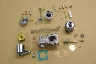
Whilst awaiting completion of machining of my Cylinder Head, rebuilding the carbs seemed to be an ideal fill in job. The spindles and main body which usually wear and allow air leaks are actually in very good condition, so its mainly a strip, clean and re-assemble exercise.
In a very senior moment whilst rebuilding my 140, I forgot that I had already bought a pair of HD6 service kits and ordered another pair (such lapses of memory do not bode well for the future I hear you say) so my only cost should be time. It all went rather well until I attempted to remove the fuel inlet union on the RH float chamber and a hairline crack appeared in the top. Burlen were out of stock, so that's another 99% completed job.
Doing one carb at a time means you can always look at the other
when you forget how it all goes back together.
All done.  Just need a new top for one float chamber.
Boot Lid
The £250 boot lid wood frame arrived on time and as requested was supplied disassembled. I would have to say, the quality of workmanship is quite exceptional. It all went together perfectly and I attached the various metal parts in order to do a trial fit. The overall size and shape looks about right and I am just awaiting the bodywork guys to fit the locking bar keeps to the body and tweak the fit.
I then need to dismantle it, paint all the steel parts with red oxide, and rebuild it inside the aluminium skin.  More on this in a future post.


Clutch shaft and fork assembly
The taper pin which engages the clutch fork on its operating shaft was still doing its job but came out in three pieces, I would think the inevitable consequence of fitting a tapered pin into a parallel hole.  The replacement item was over size but has a parallel shank so I needed to first clean up the hole in the shaft, then have the pin turned down to make it an interference fit.
The shaft bushes were also quite worn as was the carbon thrust plate on the fork, so both were replaced, the latter with a Coventry Auto Components upgraded item.

Old taper pin came out in three pieces.  New one is parallel

 Clutch shaft bushes - easy to slip in a ten thou gauge

New thrust, pins and bushes.  Bolt wiring technique is improving.
Clutch installation
With all these minor jobs completed, its time to fit the flywheel, clutch plate and cover, but first I need to ensure that the clutch plate is centrally aligned against the flywheel.  A half inch brass drift makes the ideal base for the alignment tool.  Add an old socket and some insulation tape to make up the clutch plate spline ID - perfect.

Heath Robinson clutch alignment tool
Each wrap of PVC tape increases the OD by around 4 thou
so with care, it's possible to make this a very precise device
Clutch plate and cover is now a 9.5 inch E Type spec item with
flywheel drilled and tapped to suit
Tremec Five Speed Gearbox
When I restored my 140 fixed head, I fitted a Tremec T5 gearbox. Its a superb box with a great shift action so it was an obvious choice for the 120, especially as overdrive is not an option.  It was supplied with a conversion plate to mate it to the XK bell housing - all quite straight forward.
Scary moment.  will these much modified parts really fit together?

Yes - with the usual bit of "waggling" its goes together nicely
The Tremec T5 box differs from my previous one in that it has an extra cable and plug coming from the top plate - clearly visible in the above picture, but no one seems to have a clue what its for - any ideas?
 The downside of fitting the Tremec box to a 120 is that I will need to remove some steel from the main chassis cross member and fabricate some form of rear mounting bracket.  I will cover this in detail in my next post.

Next Post - Mid June